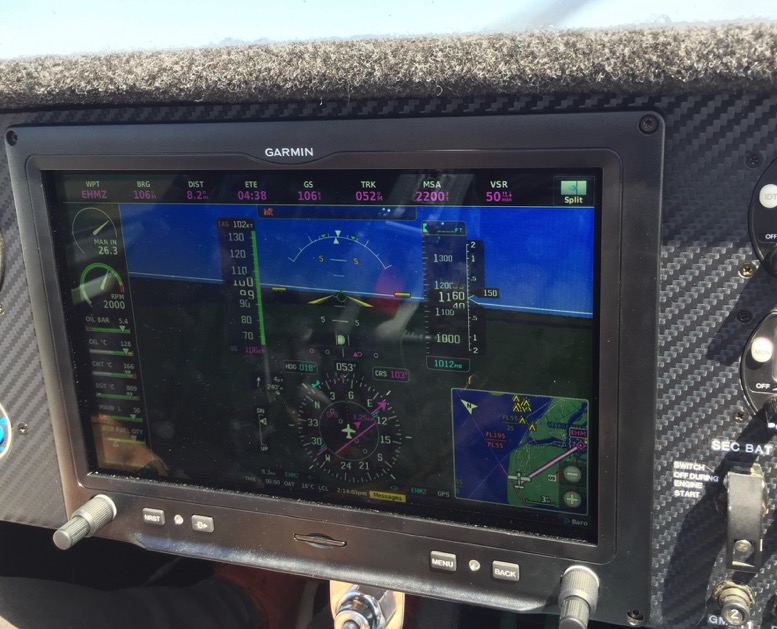
Efis
We decided to go for an Efis. Why? You have al the instruments on board, these are in one unit, so it safes a lot of space and a lot of weight. But it is really bad for your wallet. I am not a good computer guy so I decided to order an efis that will always work. Not that the other brands not work,but you can do a lot more with the other brands. That is not what I want. Simple and reliable. So I ordered a garmin g3x
The company where I ordered G3X made the basic wiring, I had to do the rest...Easy I thought
Above what I had in mind.
The GMU11
This unit is a 3-axis magnetometer. To install the GMU1, you have to follow their prescription. The installation spec for
this unit is 0.5 degrees of the centerline. It must be spirit level. It must be installed far away from magnetic field.
The stubwing location is no option because of the transponder and the fuel pumps below the seats. Best option is to install it in the tail section.
We don’t want to cut a hole in the tail section so we designed a special system
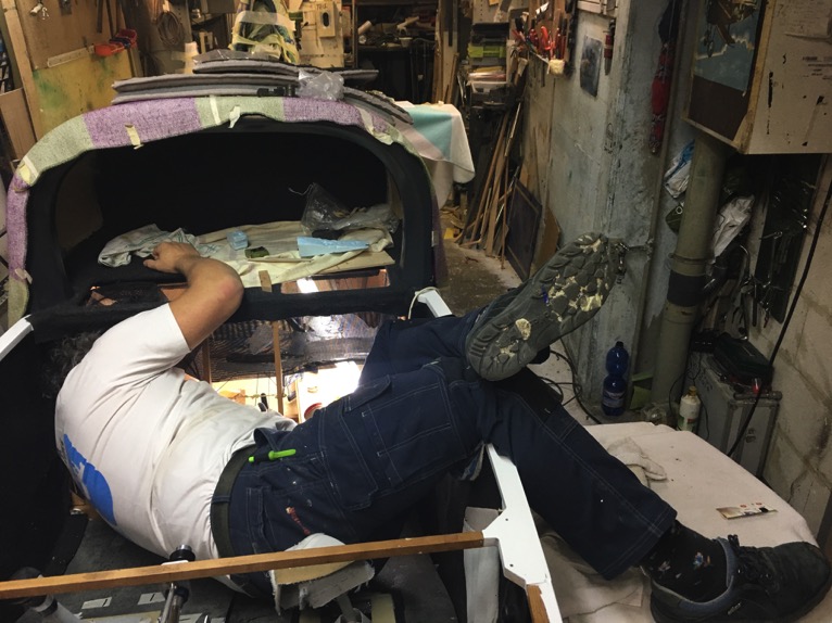
The plane is to small or I am to big.... this way is only 90 cm from the fuel pumps, so this is not the way.
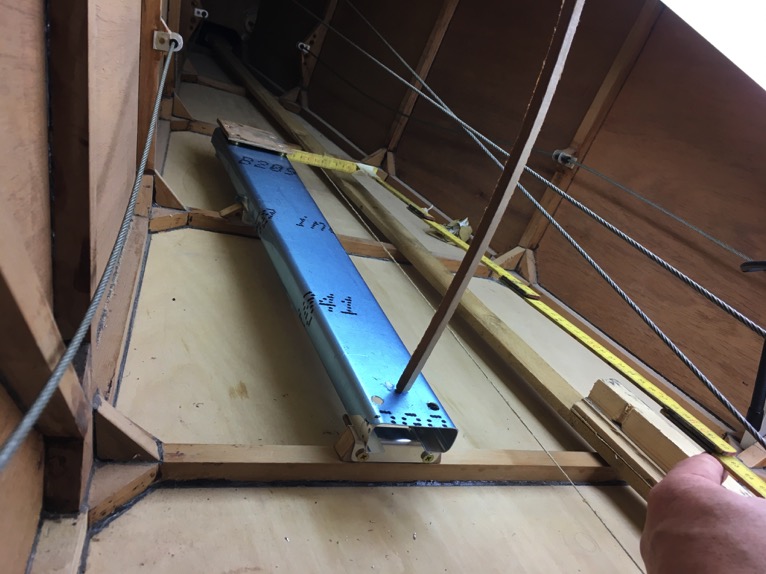
With this profile installed we extended the position with another 90 cm. The rope you see is the center line off the plane, that’s our goal to align the profile. The wooden temporary platform is spirit level, we arranged this with an phone and a level app. When it is level, the phone turned green, so the platform is ready for the GMU11. (we made a fishing stick with, at the end, the phone)

The two wooden blocks support the profile, the aft blok has 2 holes so the profile has two pin that will fit in the holes.
At the front there are two bolts.

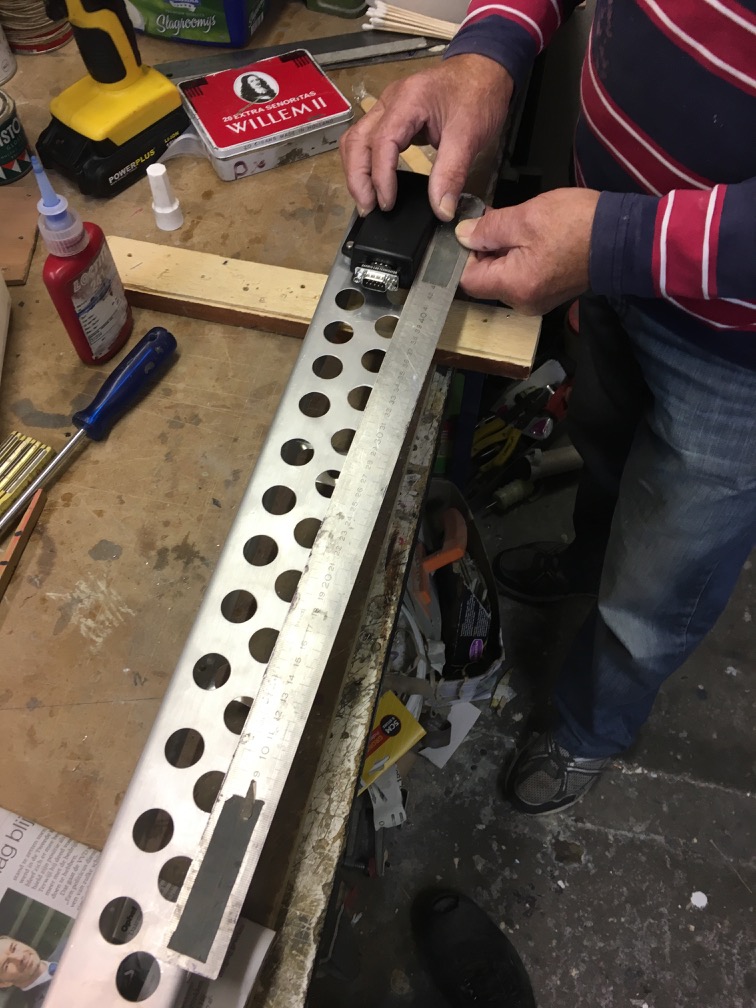
The GMU11 aligned with the profile.

ready for installation

Finished
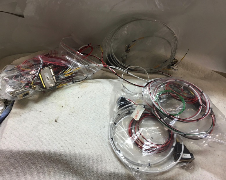
The delivered wire harness.

What a mess. First we installed everything with tyraps, later we changed this for rope.

Instrument pannel temporary installed

Fuel pump below co-pilot seat. Trig transponder below captainseat, the unit is installed on the ground plane. Trig radio behind the captainseat.

Almost finished.

In the middle the GSU 25 adahrs. The pitot-, static- and smart tube are connected with this unit. From there the pitot and the static lines are connected to the steam gages.

At the GEA 24 unit we connected all the engine sensors, and fuel tanks, trim ...........

The most of the sensor wiring is entering the fire wall at the RH side.

Making nice bundles, I could borrow the special tooling from the company I work for.
Wiring for the CHT, EGT , Fuel press, Oil press, Oil temp ect ect.
All the wiring is labeled with heat sleeve, so I can always find the wiring I need.

Almost finished.

Fire wall penetration.
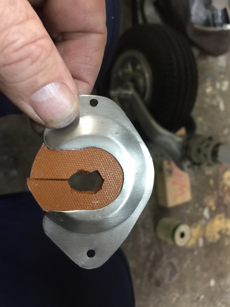
Made of very thin steel fire wall penetration plates.


I need to seal it with red RTV and than it is safe.
Oil Pressure sensor
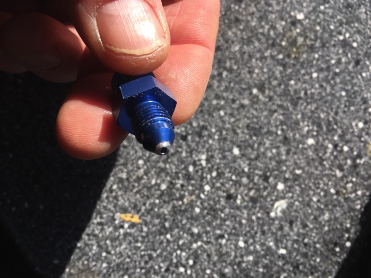
For safety reasons, I made in the AN fitting with a AD rivet, to reduce the flow. You can see the not bleu
part from the unit is the rivet with a small hole.

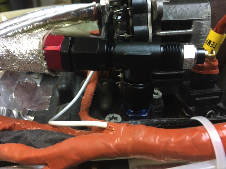
A steel line from the reduced AN fitting to the sensor

It is a bit hard to see but the sensor is mounted to bolt that goes to the engine mount. This bolt is in the quite world, so the
sensor is prevented from vibrations.
Oil temp sensor

I don’t want to have a signal mixup with the engine computer and the EFIS. So I need to have an extra oil temp sensor.
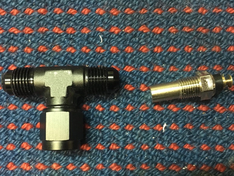
With a new AN fitting I found the solution in the T, so I can install a temp sensor.
Taps thread and the second sensor can be installed.
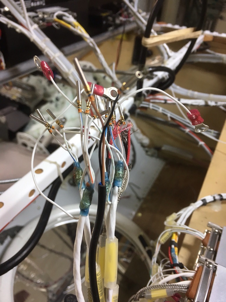
Important Tip

One of my friends had an engine failure. This was caused by a broken ring tongue. I put, at all the
important wires, an extra ring tongue.
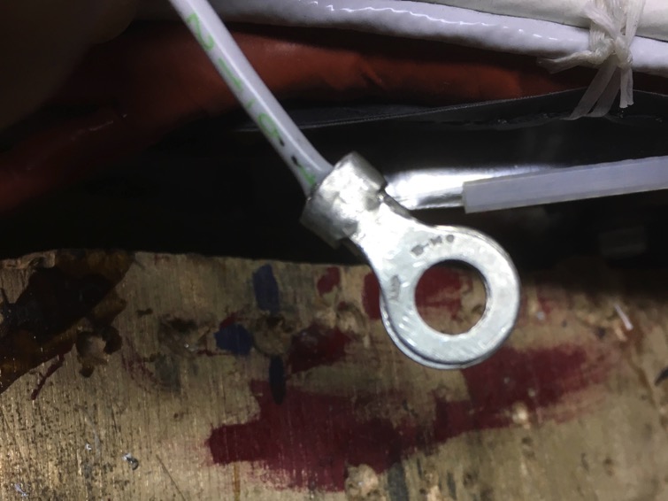
Now I know for sure it will not brake

Heat sleeve installed.mj Result a much stiffer connection.
On the back ground you see the two temp sensors.
Back to home